.png)
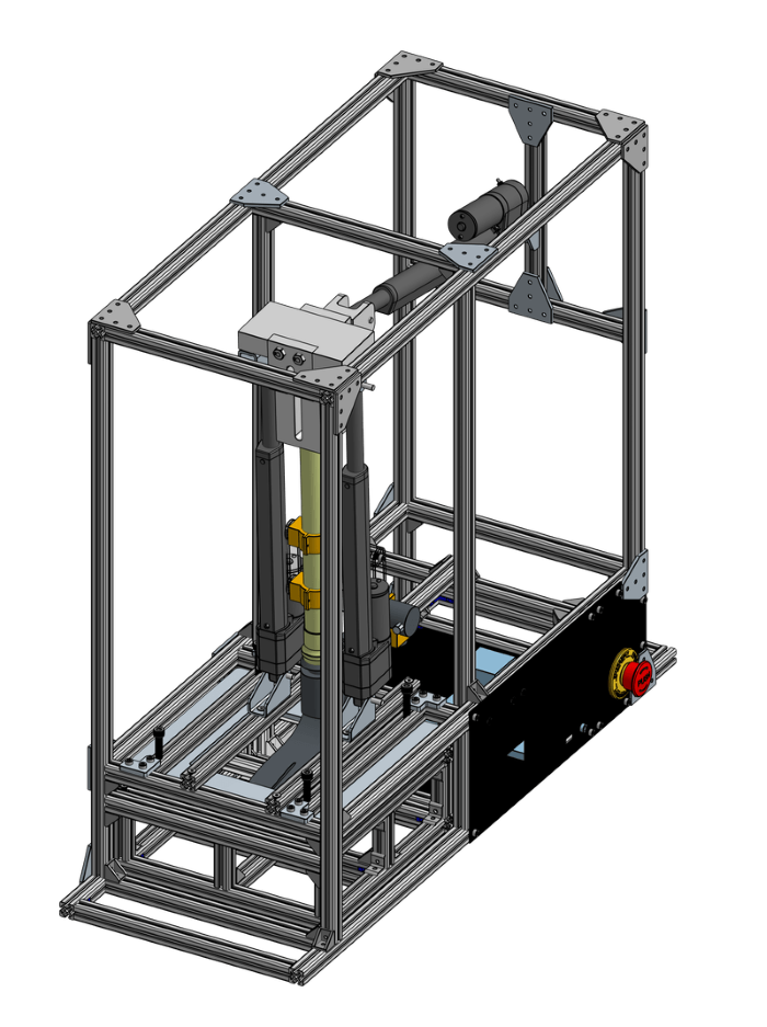
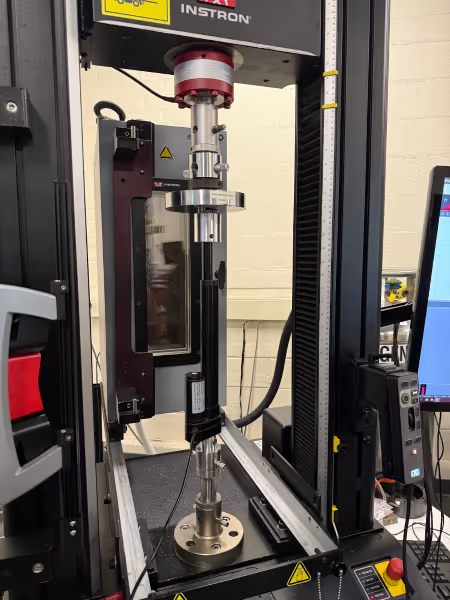
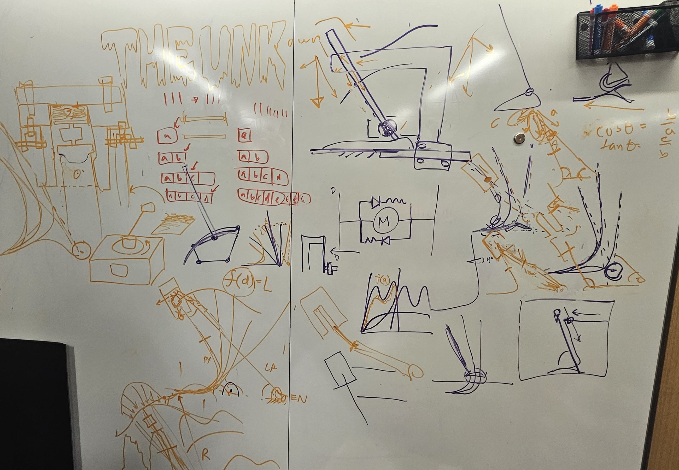
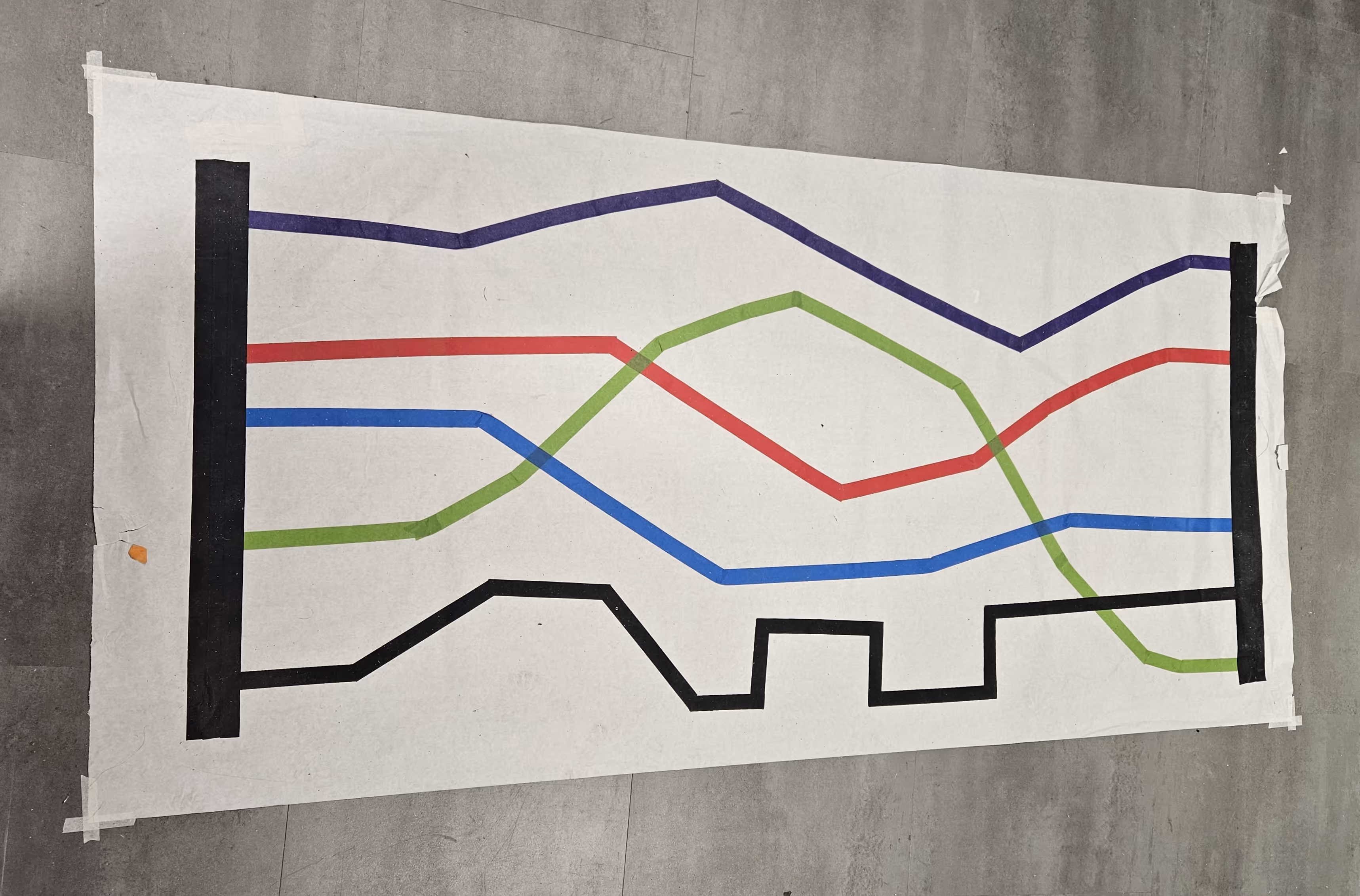
Current testing standards for prosthetic feet fail to consider how well prosthetic feet mimic the biomechanics found in anatomical human ankles in a natural walking cycle. To account for this, our client, Dr. Mark Pitkin, seeks to establish a measurable standard, the
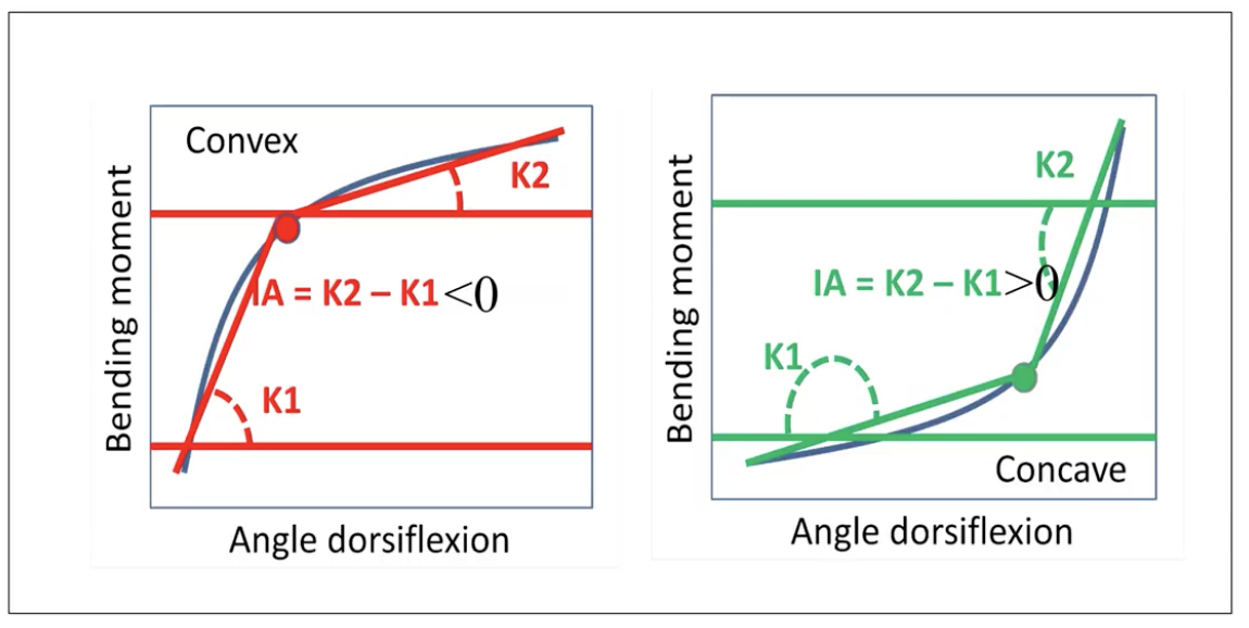
Index of Anthropomorphicity(IA). The IA quantifies the concavity or convexity of the moment-angle relationship in a prosthetic foot (moment about the ankle vs angle of deflection). In order to establish this standard, a means to reliably and accurately measure moment-angle data in a prosthetic foot during a gait cycle is necessary.
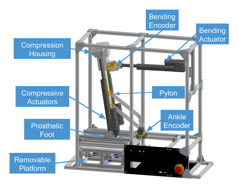


These are some initial results from our test rig. We tested the Willowwood Meta Flow foot which was designed to have a more compliant behavior that mimics the behavior seen in anatomical ankles. As can be seen in the figures, a normal anatomical ankle exhibits a concave curvature, similarly to the MF foot.
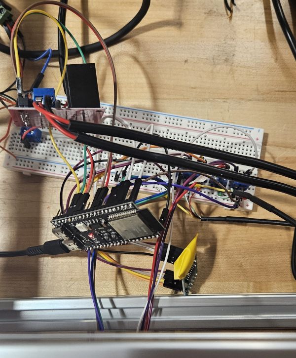
*** These results are from BEFORE we swapped the load cell for a current sensor. Moment measurement is much higher than expected


.jpeg)
.jpeg)

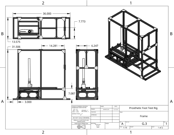
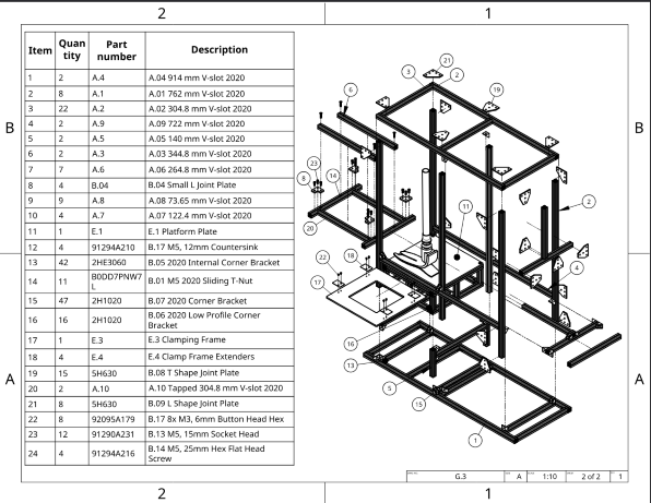
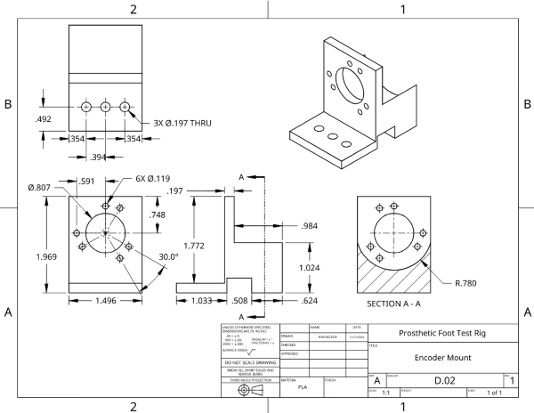


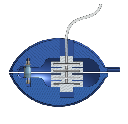

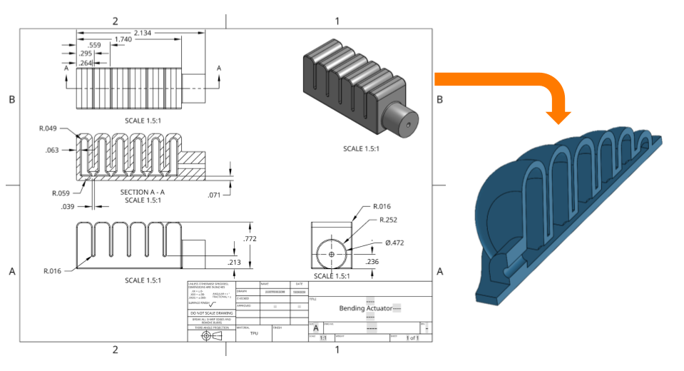


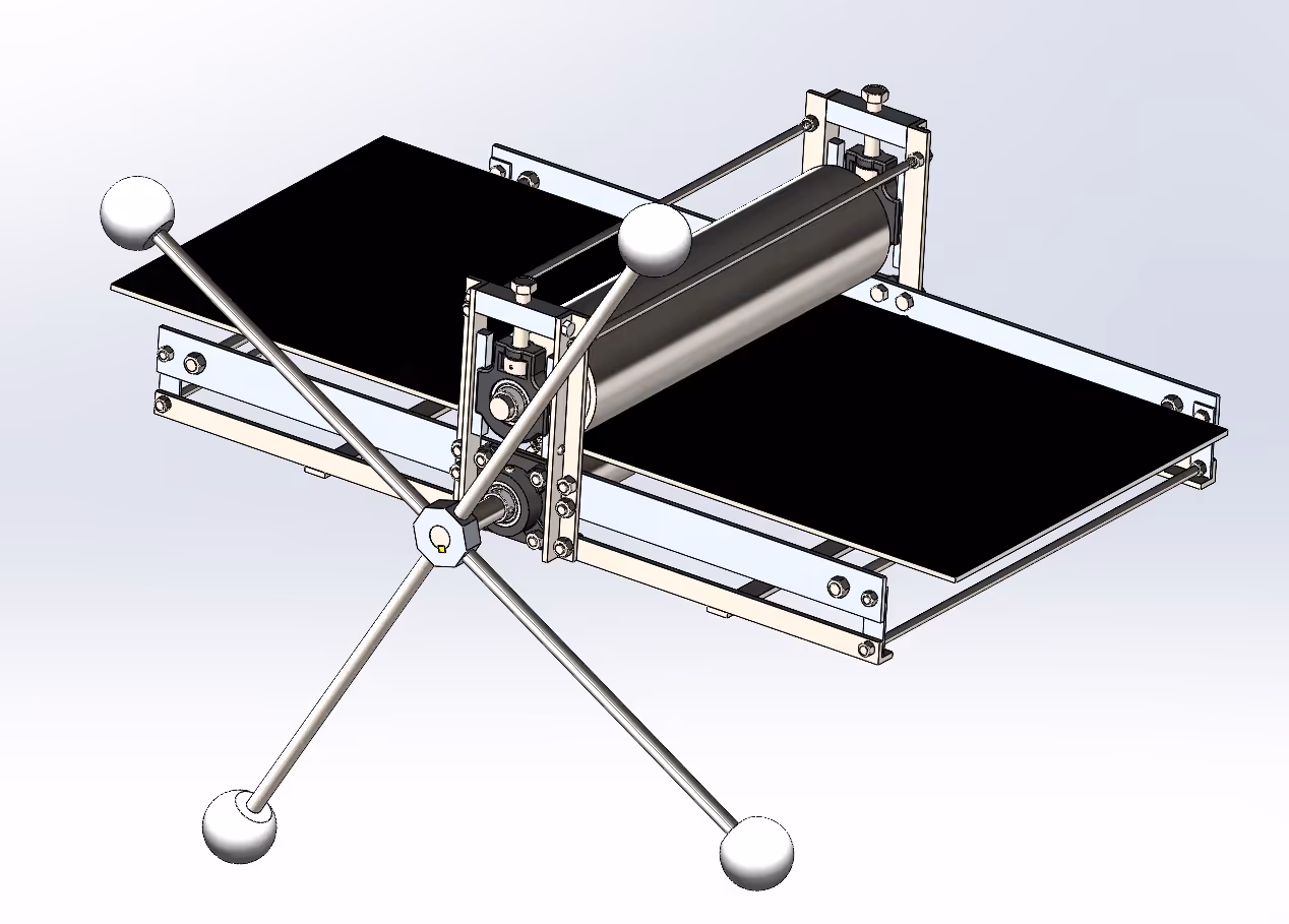
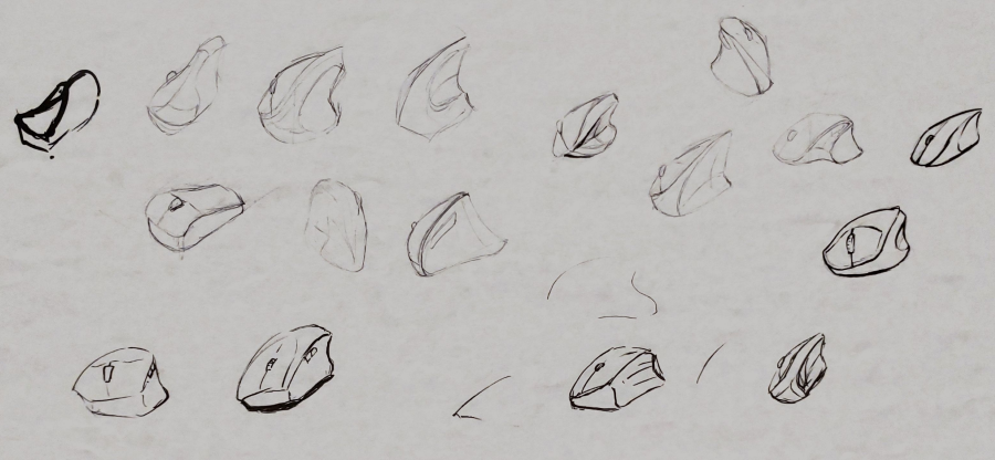
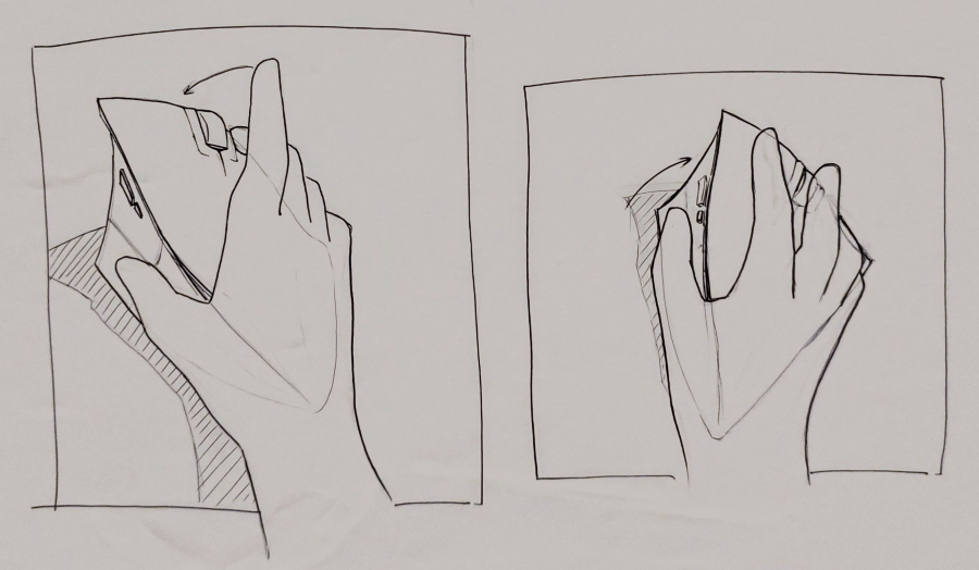
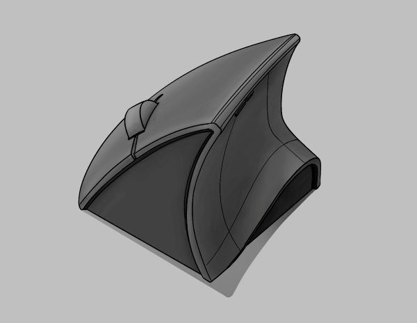
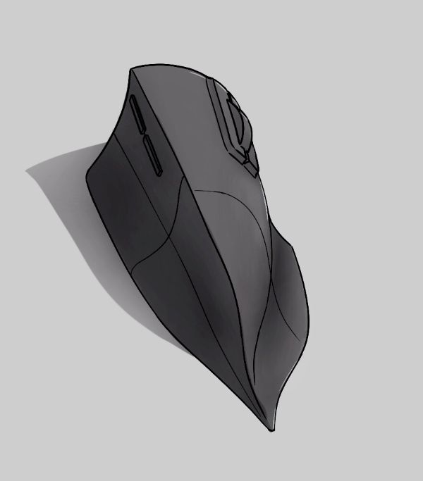
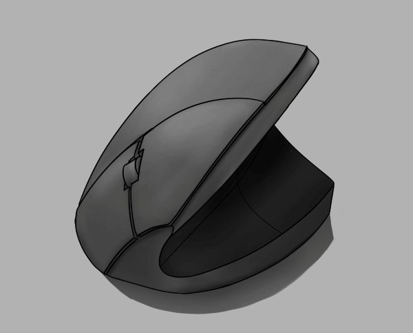
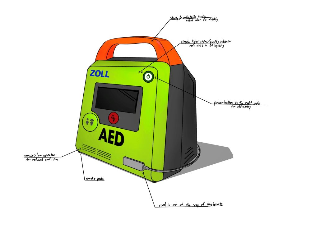
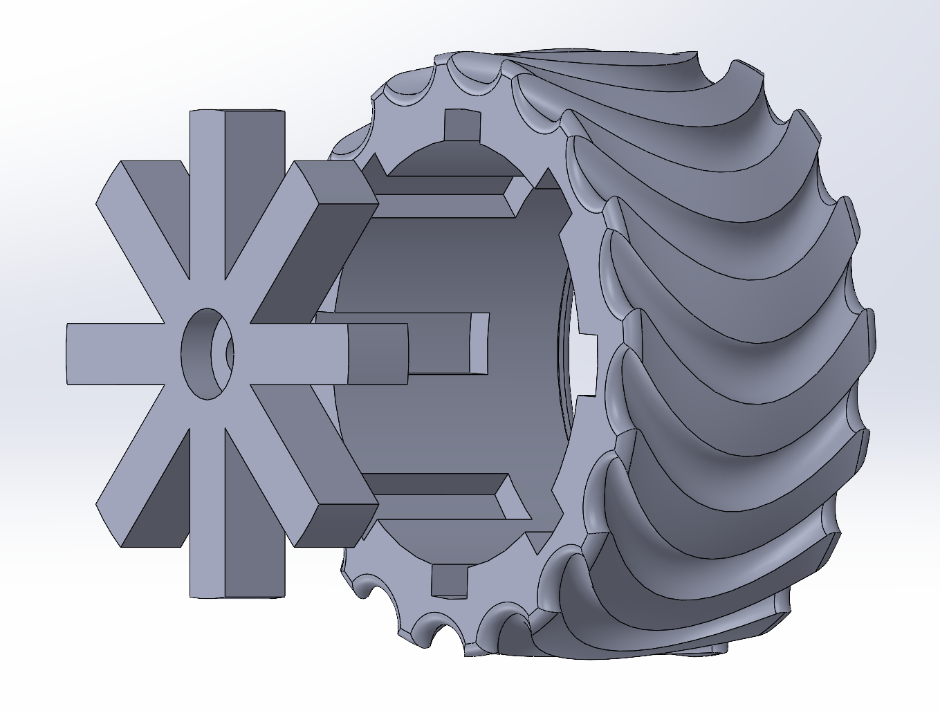
For my Computer Aided Product Design final project I was tasked to make a model and assembly of anything I wanted in Solidworks.


.jpg)
.jpg)

.jpg)


.png)


.jpg)
.png)
.png)
.png)
.jpg)
.jpg)

My name is Marinez Jose, but you can call me Nezy, and I'm a Senior studying my Undergrad in Mechanical Engineering at Tufts University. The core of my motivation stems from my sheer love of creating. For much of my life this fostered into a passion for the fine arts and has shifted gears to engineering. This continues to drive my engineering work and I feel is apparent in many of my designs. Right now I'm very interested in working in robotics, medical devices, and consumer electronics.